When conducting security analyses of IoT devices, it is often worthwhile to take a closer look at the hardware. In this blog post, we examine the serial UART interface of the IoT camera. The goal is to determine what information can be read via this interface and whether it can be used to gain deeper access to the system.
Examination of the UART Interface
During the initial visual inspection of the hardware, three adjacent pins were identified:
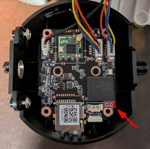
Since the three pins are located in the immediate vicinity of the microcontroller, it is highly likely that this is a UART interface. UART (Universal Asynchronous Receiver / Transmitter) typically uses two data lines – Tx (Transmit) and Rx (Receive) – as well as a GND pin (Ground). In some cases, a fourth pin exists for the power supply (typically 3.3 V or 5 V).
To determine the function of the individual pins – i.e., GND, Tx and Rx – there are several options. Either automated (for example, with a logic analyzer) or manually with a multimeter. In all cases, however, at least GND must be identified.
A simple continuity test with a multimeter can be performed for identification. One probe is held on the pin to be tested and the other on a known ground point (e.g., contacts around the screws). The multimeter emits a beep, indicating a direct connection – so the pin is GND.
The other two pins can be identified by observing the voltage when the camera boots. If there is a strong voltage fluctuation during the boot process in the first 10-15 seconds, this is the Tx-Pin. However, if the voltage is relatively low, this is the Rx-Pin.
The following pin layout was identified using this method:
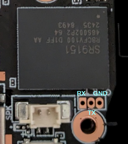
A cable is soldered to each pin for further analysis. A simple TTL-232R-3v3 cable (https://ftdichip.com/products/ttl-232r-3v3/) can be used for interactive communication.
The standard configuration for many devices is a baud rate of 9600 or 115200, 8 data bits, active stop bit, no flow control (Flow Control) and no parity bit (Parity Bit).
For communication, Screen can be used, for example (https://linux.die.net/man/1/screen):
screen /dev/ttyUSB0 115200
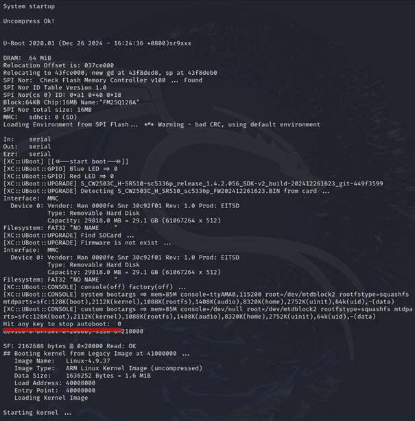
Bingo! The boot process will be completed and the output will appear in the console.
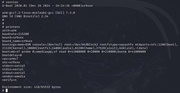
Upon closer inspection of the U-Boot output, it is evident that the variable bootdelay is set to 0 . Developers often assume that this makes it impossible to halt the boot process. However, this is a fallacy: Even with bootdelay=0 , U-Boot still checks at startup whether the key combination CTRL-C is pressed (see: U-Boot Documentation – Environment Variables).
This means that the boot process can still be stopped manually in this case, provided the appropriate key combination is pressed at the right moment.
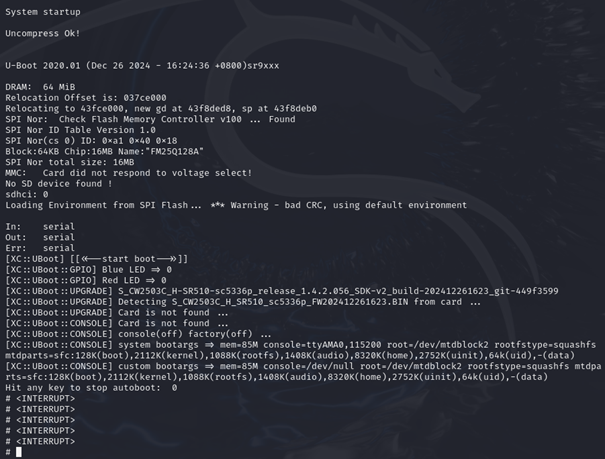
The boot process is interrupted, and various U-Boot commands can be used, e.g. version (output of the U-Boot version) and printenv (output of the environment/boot variables).
Without the previously obtained access to the firmware (see Part 1), the U-Boot shell could also have been used to interact directly with the memory and extract the firmware.
However, the attempt to change the boot arguments in such a way that an unauthenticated system shell is called failed. Changing the boot arguments even caused the device to no longer start. Only by reflashing the original firmware using an in-circuit programmer could the camera be put back into operation.
Changing the root password via various methods (e.g. calling passwd in HOOK.sh) also failed, ultimately because the setuid-bit was not set in the passwd-Binary. In addition, the file system is mounted as read-only, which means that no changes can be made.
Through access to the firmware (see Part 1) could in the /etc/init.sh the following query can be identified:
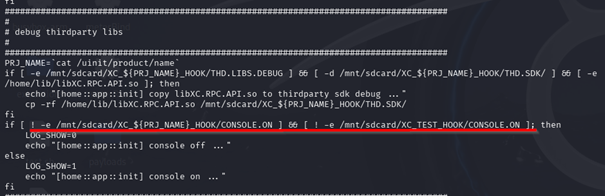
The output of the logs via the console can be activated if a file named CONSOLE.ON is placed on the SD card.
The outputs then contain a wealth of useful information, such as the individual partitions in memory (MTD partitions):
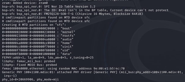
This largely confirms the memory areas identified by binwalk :
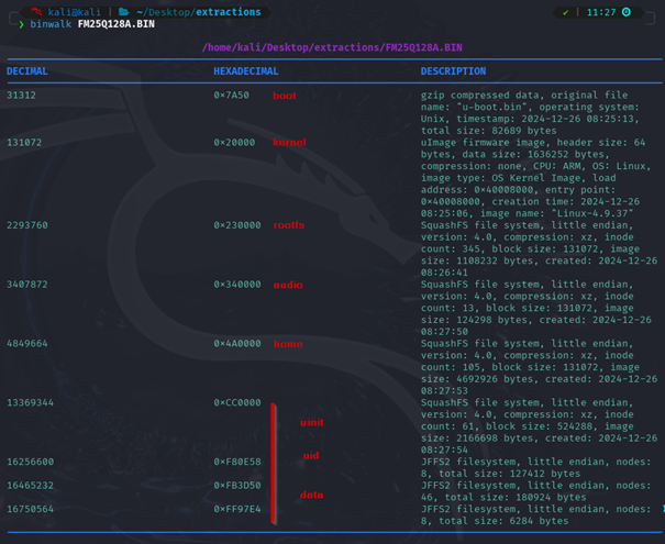
Only the uinit-, uid- and datapartitions were not correctly recognized by binwalk .
However, these can be manually extracted from the firmware dump using dd .
Here as an example for the datapartition:
dd if=FM25Q128A.BIN of=data bs=1 skip=$((0xF80000)) count=$((0x1000000-0xF80000))
With the Linux tool file , it can then be confirmed that it is a jffs2 file system, which can be unpacked with jefferson (https://github.com/sviehb/jefferson):
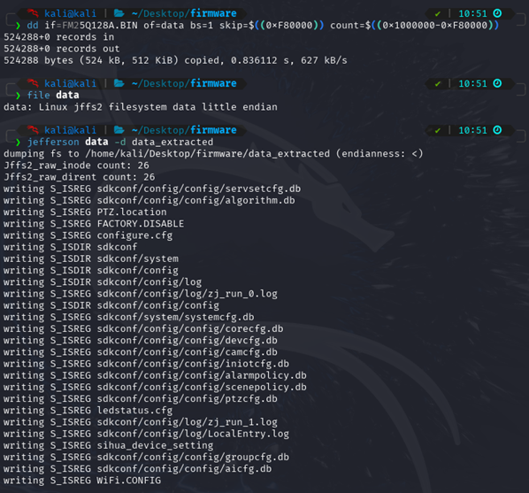
With the help of the console output, the complete firmware could be reconstructed from the flash dump.
The console now also displays a login prompt. However, since it was not possible to crack the password of the rootuser, and changes to the bootloader configuration led to a faulty boot process, access to the device is not possible, at least via the UART interface.
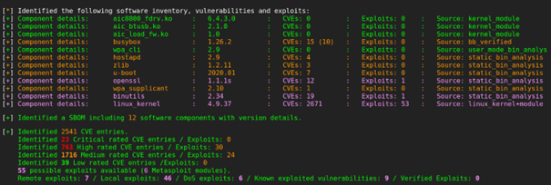
The firmware was finally analyzed with the EMBA tool (https://github.com/e-m-b-a/emba). This identified indications of further vulnerabilities in outdated software.
The majority of the vulnerabilities are found in the outdated Linux Kernel. Exploits are available for some of them.
Summary
In our blog post series, we have shown how easily in-depth information can be obtained from inadequately protected IoT devices. A key result was the complete recovery of the firmware from the read-out flash memory. This not only provided insights into the functioning of the device, but also identified security vulnerabilities that could be used to completely take over the device.
Full access to the camera not only means that sensitive user data, including the WLAN access data and the user name or associated email address used in the app, can be read out. This security vulnerability could also allow attackers to access central functions of the camera – such as the live stream of the camera, the microphone or the intercom function. This quickly turns a simple camera into a gateway into the entire home network, which could make not only the device itself, but also potentially other systems in the home network vulnerable.
Such vulnerabilities raise fundamental security concerns regarding the handling of networked devices, especially when they lack effective protection mechanisms against unauthorized access. In real-world scenarios, attackers could not only compromise privacy and data but also prepare attacks on other devices within the same network.
In a more in-depth firmware analysis, further sensitive information and software vulnerabilities could be identified, such as running services, insecure update mechanisms, or configuration errors. The communication between the camera, the associated cloud infrastructure, and the mobile app would also typically be part of a comprehensive IoT pentest.
However, since the focus of this analysis was on the hardware and further tests would have required a direct examination of the manufacturer's systems, this was deliberately omitted in this case.